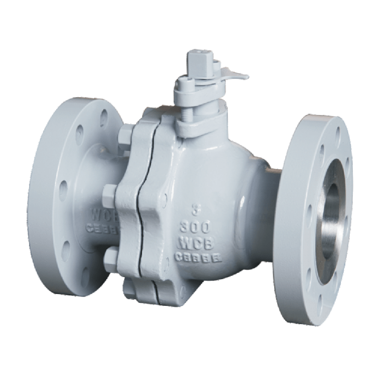
ANSI Class 300 Flanged Ball Valve is made of stainless steel and carbon steel. Large diameter can be equipped with Gear Operated. The upper flange conforms to ISO 5211 standard, so it can also become a pneumatic flanged ball valve and an electric flanged ball valve.
Stainless Steel ANSI Class 300 Flange Ball Valve Structure diagram

| NO | PAPT NAME | MATERIAL |
| 1 | screw | B7/304 |
| 2 | Washer | 1020/304 |
| 3 | Handle | WCB |
| 4 | Retaining ring | 60Mn/304 |
| 5 | screw | B7/304 |
| 6 | Gland | WCB/304 |
| 7 | Packing | SCPH2/SCS13 |
| 8 | Packing | PTFE |
| 9 | Thrust Gasket | PTFE |
| 10 | Stem | 304/316 |
| 11 | Gasket | PTFE |
| 12 | Bonnet | WCB/CF8/CFBM |
| 13 | Nut | 2H/304 |
| 14 | Stud | B7/304 |
| 15 | Ball | 304/316 |
| 16 | Body | WCB/CF8/CFBM |
| 17 | Seat | PTFE |

Chinese Flanged ball valve made in China-Product advantages
- The valve blank is precision cast with high strength
- The valve ball is a solid ball with high pressure
- The ball valve aisle can be polished, suitable for some special media
- The valve paint is sprayed with epoxy resin, and the carbon steel ball valve is also durable
- Each valve is tested for 1-2 minutes before leaving the factory, and the product quality is high.Simple structure, small volume and light weight.
Forged F304 Class 300 Ball Valve

ANSI Class 300 Flanged Ball Valve explain
The stainless steel Class 300 ball valve body is mainly composed of two-piece casting, the middle seat material can be selected from PTFE and PPL, and the valve is a full-bore aisle.

Stainless Steel ANSI Class 300 Flanged Ball Valve Main External and Connecting Dimensions
| NPS | D1 | d | K | D | C | f | N-OZ | L | H E | E |
| 1/2″ | 15 | 34.9 | 60.3 | 90 | 14 | 1 | 4-16 | 108 | 79 | 125 |
| 3/4″ | 20 | 42.9 | 69.9 | 100 | 16 | 1 | 4-16 | 117 | 82 | 125 |
| 1″ | 25 | 50.8 | 79.4 | 110 | 16 | 1 | 4-16 | 127 | 102 | 155 |
| 1 1/4″ | 32 | 63.5 | 88.9 | 115 | 18 | 2 | 4-16 | 140 | 106 | 155 |
| 1 1/2″ | 38 | 73 | 98.4 | 125 | 18 | 2 | 4-16 | 165 | 128 | 240 |
| 2″ | 50 | 92.1 | 120.7 | 150 | 18 | 2 | 4-19 | 178 | 135 | 240 |
| 2 1/2″ | 65 | 104.8 | 139.7 | 180 | 20 | 2 | 4-19 | 190 | 145 | 280 |
| 3″ | 78 | 127 | 152.4 | 190 | 22 | 2 | 4-19 | 203 | 160 | 320 |
| 4″ | 98 | 157.2 | 190.5 | 230 | 24 | 2 | 8-19 | 229 | 180 | 320 |
| 5″ | 123 | 185.7 | 215.9 | 255 | 26 | 2 | 8-22 | 356 | 252 | 530 |
| 6″ | 148 | 215.9 | 241.3 | 280 | 28 | 2 | 8-22 | 394 | 285 | 630 |
| 8″ | 198 | 269.9 | 298.5 | 345 | 30 | 2 | 8-22 | 457 | 385 | 800 |
| 10″ | 248 | 323.8 | 362.0 | 405 | 34 | 2 | 12-25 | 533 | 485 | worm gear |
| 12″ | 298 | 381.0 | 431.8 | 485 | 36 | 3 | 12-25 | 610 | 545 | worm gear |
| 14 | 348 | 412.8 | 476.3 | 535 | 44 | 3 | 12-25 | 686 | 635 | worm gear |
Design Standard: ASME B 16.34
Construction Length: ASME B 16.10
Flange Standard: ASME B16.5
Inspection and Testing: API 598
- Nominal pressure or pressure class: pn1.0-32.0mpa, ANSI class 150-900, jis10-20k;
- Nominal diameter or diameter: dn6 ~ 900, NPs 1 / 4 ~ 36;
- Connection method: flanged
- Applicable temperature: – 196 ℃ ~ 540 ℃;
- Driving mode: manual, worm gear and worm drive, pneumatic, electric, hydraulic, pneumatic hydraulic linkage, electro-hydraulic linkage;
Features
1. The valve stem has an anti-static setting
2. The valve stem is designed with an anti-disengagement device.
3. There is a pressure relief hole design on the ball groove of the steel ball.
4. Adopt ISO 5211 direct installation actuator platform design.
